While solar would seem like the ideal solution, quite often this is not possible due to location and shading problems. Just such a situation arose when I decided to make our new gates automatic. There were just too many trees in the way for solar power to work, and I didn’t want to run power some 30 metres or so from the house, as it would have meant digging a trench for the cables, which is almost impossible in our rocky ground.
Why have automatic gates anyway? Well, our driveway and the one next door share a common entrance, so to open the gates we have to block their driveway. Also, the driveways are very steep, and starting off driving up from a standstill is not too good for the vehicle’s clutch. Besides, when an opportunity arises to install some form of new renewable energy device, how can I say no?
Anyway, I decided to provide power to the electric gate openers from a small wind turbine. While we don’t have many windy days, we do have one or two each fortnight where the wind blasts through for at least 24 hours solid, so I guessed that I should be able to power a device with such modest power requirements as a gate opener in this way.
The gate opener system itself is a home-made job, using car windscreen wiper motors driving long brass threaded shafts. These run through a nut which is attached to the gate via a steel tube, bolt and two metal rackets. The motors are hinged, and when they are run they either push the nut away from them or pull it toward them, thus opening and closing the gates. The control circuit for this is a kit purchased from Oatley Electronics in Sydney, and includes a courtesy light function, remote control, and motor current sensing.
This type of vertical axis rotor is very robust and durable if built correctly, is relatively slow turning and can be easily built at home, without the hassles of aerofoil blade design and other problems associated with horizontal axis ‘propeller’ type turbines.
What’s more, unlike a horizontal axis turbine, a Savonius is always facing the wind, and more importantly for this site, is not badly affected by turbulence, which is quite high where the turbine had to be located.
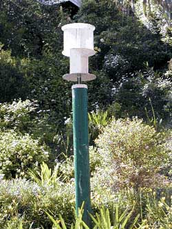
As can be seen from the photo, the turbine is mounted quite low due to it being on a residential block. While this is far from optimal, it should provide enough power for the gate openers providing it is used with a battery of relatively high capacity.
The axle for the rotor was a length of 40mm diameter water pipe. This runs straight through the centre of all three disks, and the inner edge of each of the rotor vanes are riveted to it.
In the bottom end of the axle I pressed in (read hammered) an aluminium adapter bushing to allow the turbine to be connected directly to a generator. The final assembly was very strong and rigid and was surprisingly well balanced. While a central axle shaft is not considered optimal design for a Savonius rotor, it does have advantages, such as increasing turbine strength and allowing easy alignment in multi-stage rotors.
Savonius designThere are several variations of Savonius rotor that I have seen, all of which work well. The efficiency of a Savonius is only around 15 per cent but they are ideal for many situations. Some variations are shown below, looking down from the top of the turbine. |
 This is the design I used. It is very strong due to the
central shaft, but sligtly less efficient than the other two. However, the
extra strength allows the rotor to be supported at one end only. This is the design I used. It is very strong due to the
central shaft, but sligtly less efficient than the other two. However, the
extra strength allows the rotor to be supported at one end only. |
 This design is also very simple, and can also be made easily
from metal drums or pipe sections. The design is slightly more efficient
than the one above as some of the air is deflected by the second vane as
it exits the first one. This design is also very simple, and can also be made easily
from metal drums or pipe sections. The design is slightly more efficient
than the one above as some of the air is deflected by the second vane as
it exits the first one. |
 This is the most efficient Savonius design. It not only has
the advantage of air being deflected twice like the design above, but also
that the vanes act partly like an airfoil when they are edge-on into the
wind, creating a small lift effect and thus enhancing efficiency. This
design is much more difficult to build, requiring vanes rolled from metal
sheet instead of being cut from drums or pipes. This is the most efficient Savonius design. It not only has
the advantage of air being deflected twice like the design above, but also
that the vanes act partly like an airfoil when they are edge-on into the
wind, creating a small lift effect and thus enhancing efficiency. This
design is much more difficult to build, requiring vanes rolled from metal
sheet instead of being cut from drums or pipes. |
The rotor slides directly onto the end of the motor shaft, and is held in place with a stainless steel bolt. In this design, I decided to see if I could do away with having a top bearing. The bearings in the tape drive motor are at least as strong as the average car alternator bearing, and the local bearing shop gave me specs that indicate that most bearings this size will take a radial load (the load the wind would place on the bearing) of up to 450kg, and an axial load (the load from the rotor’s weight) of up to 45kg. This was heaps for my uses, so I decided to leave out the top bearing and see how the turbine went.
By itself, this would not have been strong enough, as the end cap would have flexed and eventually broken through, so I attached three short braces made from 25 x 25 x 3 plastic angle to the other end of the generator. These were fixed to the motor using machine screws into the bottom end plate, and point out away from the centre of the generator. The overall diameter of the circle they make is the same as that of the inside of the pipe, so that when the generator is slid into the pipe the whole assembly is quite solid.
Hopefully, this will be all that is required, but I suspect that the end cap may still not be quite strong enough, so I might have to replace it with a metal equivalent further down the track.

Some time back a circuit was published in one of the electronics magazines that allowed a 12 volt battery to be charged from another. This was used for charging small sealed-lead acid batteries from a car battery, and involved a switchmode step-up circuit to provide a regulated 13.8 volts or so from 12 volts from the car battery.
I have built several of these from various suppliers, and they work quite well. The one I used I already had from another disused project, so I tested it and found that it would output the required 13.8 volts from as little as four volts in. This kit was originally bought from Jaycar Electronics, who no longer sell it, but they do have a pre-built module called a solar power converter, cat# AA-0259, that will take an input voltage from one to ten volts and charge a 12 volt battery—perfect for uses such as this.
The unit seemed ideal for my turbine so I connected it to the generator and tested it. At under 200 RPM I was getting full charging voltage, with available current increasing as rotor speed increased.
The mast and turbine were both painted green to help them blend in with their surroundings. The photos show the turbine before its paint job.
To prevent water getting into the generator bearing, a skirt will be attached around the perimeter of the bottom of the turbine.
 The DC motor fitted to the plastic end cap which holds it to
the mast. The DC motor fitted to the plastic end cap which holds it to
the mast.
|  Front view of the motor. Note the threaded holes in the face
plate. Front view of the motor. Note the threaded holes in the face
plate. |
 This rear view shows the three plastic angle sections used to
make the motor a tight fit in the mast. This rear view shows the three plastic angle sections used to
make the motor a tight fit in the mast.
|  Here you can see the whole motor and rotor assembly before
fitting to the mast and painting. Note how the vanes in the top section
are rotated 90° to those in the bottom section, and the motor does not yet
have the plastic angle sections attached. Here you can see the whole motor and rotor assembly before
fitting to the mast and painting. Note how the vanes in the top section
are rotated 90° to those in the bottom section, and the motor does not yet
have the plastic angle sections attached. |
The only other expenses were a dollar or two worth of paint and rivets and $5
for a bag of concrete. 